Reading a Boat Wiring Diagram

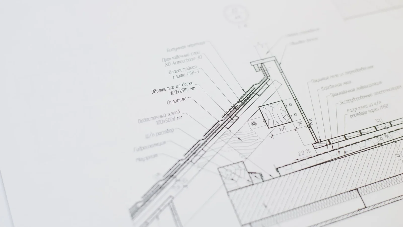
A wiring diagram looks like a subway map drawn by someone who hated you. Lines cross, little symbols repeat, numbers hang off the ends of wires with no explanation, and somewhere in that mess is the reason your anchor light won’t come on. I have watched capable people close the manual and reach for a multimeter out of pure frustration, when the answer was sitting right there on the page.
The skill of reading a boat wiring diagram is not electrical genius. It is more like learning to read a recipe: once you know what the symbols mean and which way the story flows, the whole page settles down and starts telling you exactly where to put your hands.
That is what this walkthrough gives you, step by step, using a real bilge pump circuit with real numbers so nothing stays abstract.
Tools You Actually Need at the Table
You do not need much to read a diagram, and most of it you already own. The point is to slow yourself down and mark the page as you go.
- A printed copy of the diagram, or a tablet you can zoom on. Zooming beats squinting.
- Two or three highlighters in different colors, roughly a dollar each.
- A pencil for notes in the margin.
- A basic multimeter (a $30 unit is fine) for confirming what the diagram claims once you move to the boat.
If you are brand new to any of this, the 12V Boat Wiring Guide for Beginners is the pillar this article hangs off, and it covers the vocabulary I’ll use below without over-explaining every term.

Step 1: Find the Two Ends of the Story
Every DC circuit on a boat is a loop that starts and ends at the battery. Before you read anything in the middle, put your finger on the two ends: battery positive (usually marked with a plus sign, often red) and battery negative, also called ground (a minus sign, often black or yellow).
On most diagrams, positive lives at the top or the left, and ground runs along the bottom or returns to a common bar. Current leaves positive, does its work, and comes home to negative. If you know only that, you already know which direction to read.
Step 2: Learn the Handful of Symbols That Matter
Small-boat diagrams reuse the same short alphabet. Memorize these and the page stops being hieroglyphics.
| Symbol | What it means | What it does in the circuit |
|---|---|---|
| Long and short parallel lines | Battery | The source. Long line is positive, short line is negative. |
| Small rectangle or a wavy line | Fuse | Protects the wire by blowing before the wire overheats. |
| A break with a hinged line | Switch or breaker | Opens or closes the loop to turn a load on and off. |
| Circle with a label | Load (pump, light, motor) | The device doing the work and drawing the current. |
| Three shrinking horizontal lines | Ground | The return path to battery negative. |
| A dot where lines cross | Connection | Wires join here. No dot means they cross without touching. |
That last one bites people constantly. A dot means the wires are joined; no dot means one hops over the other. Misread it and you’ll assume a connection that isn’t there, or miss one that is.
Step 3: Read the Wire Labels, Not Just the Lines
The lines show you the path. The little tags on the lines tell you the specifics, and they are where the real information hides.
A label like 16 AWG means 16-gauge wire, where a bigger number is thinner wire. You’ll also see color codes, and on a proper boat those follow a standard: red or a numbered code for positive, yellow for the DC negative on newer builds, and specific colors for pumps, lights, and instruments so the next person can trace your work.
Gauge is not decoration. It is chosen for two reasons at once: carrying the amps without overheating, and delivering voltage to the far end without losing too much along the way. If a label surprises you (say, 10-gauge feeding a small light), that usually means a long run where Understanding Voltage Drop on Boats forced a heavier wire. The full method for picking a size lives in How to Choose Marine Wire Gauge.
Step 4: Trace One Complete Loop
Here is the move that separates people who read diagrams from people who stare at them. Pick one circuit and highlight the entire loop, start to finish, before you look at anything else on the page.
Start at battery positive. Follow the line through the fuse, through the switch, into the load, and back along the ground to negative. Run a highlighter over every segment as you go. If your highlighter reaches a dead end or the line vanishes into a bundle, that is a clue, not a failure, and it usually means a bus bar or a connector you need to find on the boat.
A Worked Example: The Bilge Pump Circuit
Let me put numbers on a circuit you’ll meet on almost every boat. This is a bilge pump I traced on a 24-foot cuddy last spring, and the diagram told the whole story once I read it in order.
Following the loop from the top:
- Battery positive, 12V, feeds a bus bar.
- A 3-amp fuse sits within a few inches of that bar (the diagram labeled it “3A”).
- From the fuse, 16 AWG brown wire runs to a three-way switch marked OFF / AUTO / MANUAL.
- In AUTO, the wire routes through a float switch that closes when water rises.
- The wire reaches the pump, a circle labeled “Rule 500, 2.5A.”
- Yellow ground returns from the pump to the negative bus, and home to the battery.
Now the numbers make sense. The pump draws 2.5 amps, so a 3-amp fuse is on the small side but plausible for a short run, and 16-gauge is fine for that current over maybe 10 feet round-trip. When the owner’s pump ran but the AUTO mode did nothing, the diagram pointed straight at the float switch as the only part unique to AUTO. It was corroded. Fifteen minutes, one connector, done.
Step 5: Cross-Check the Diagram Against the Boat
A diagram is a promise. The boat is the truth. Once you’ve traced a loop on paper, go find those same parts in the real hull and confirm they match.
Set your multimeter to DC volts and check that you read roughly 12 to 12.7 volts across the battery, then work down the circuit confirming voltage appears where the diagram says a live wire should be. If the diagram shows a fuse and you find a length of bare wire jammed into a holder, you’ve just learned why nothing on that circuit is trustworthy.
For the AC side of a boat, shore power and inverters, the diagrams get denser and the stakes climb because 120 volts can kill you. If your schematic includes an inverter or charger, walk through the Boat Inverter and Charger Guide first, and consider having an experienced hand check your reading before you wire anything.
Where the Symbols Come From
Most marine diagrams borrow their symbols from standard electrical schematic conventions, so once you learn them here they carry over to your outboard manual, your chartplotter install sheet, and beyond. If you want a reference for the symbols themselves, the standard electronic symbol reference covers the shapes you’ll keep running into. For plain-English boat electrical safety that lines up with how these systems should be built, BoatUS publishes guidance worth a read.
Put It to Work on Your Own Boat
Pick the simplest circuit you have, a cabin light or that bilge pump, and trace it end to end with a highlighter tonight. Name every symbol out loud as you pass it. Do that once and the next diagram will feel half as intimidating.
The page was never trying to confuse you. It is just a map of a loop, drawn in shorthand, and now you speak the shorthand. Follow the current from positive, through the fuse and switch, into the load, and back to ground, and there is very little on a small-boat diagram you can’t read.
Frequently asked questions
Which way does current flow on a boat wiring diagram?
Current leaves battery positive, travels through the fuse, switch, and load, then returns through the negative ground back to the battery. On most diagrams positive sits at the top or left and ground runs along the bottom. Reading in that direction keeps the whole loop in order.
What do the ground symbols on a wiring diagram mean?
The small stack of shrinking horizontal lines is a ground symbol, and it represents the return path to battery negative. Many diagrams draw several separate ground symbols instead of one long wire, but electrically they are all the same point. Treat every ground symbol as a doorway straight back to the battery negative.
How do I know if two wires connect where they cross?
Look for a dot at the crossing point. A dot means the two wires are joined together, while no dot means one line simply hops over the other without touching. Misreading this single detail is one of the most common tracing errors, so check every crossing.
What does a label like 16 AWG mean on the diagram?
AWG stands for American Wire Gauge, and 16 AWG means 16-gauge wire, where a larger number is a thinner conductor. The gauge is chosen to carry the circuit amps safely and to limit voltage drop over the run. A surprisingly heavy gauge on a small load usually signals a long wire run.
Should I trust the wiring diagram over the actual boat wiring?
No. A diagram shows how the boat was designed, not how a previous owner may have modified it. Always confirm the real wiring with a multimeter before you cut or replace anything. Use the diagram as a map and the boat as the final word.